
Daming Gao
Engineering Design Portfolio
Matboard Bridge Design
Our second project in CIV102 was to build a matboard bridge. The only allowable materials were a piece of matboard whose dimension is 32''*40''*0.05'', and two tubes of contact cement. The bridge has to span 990mm and the point loads will be applied 300mm away from the edges. Since the material was very limited, we could not make any mistakes as we implemented our design. As a result, meticulous preparations were needed.
Generate Solutions/Best Solution
(1) Brainstorm any possible designs (consider the possible shapes of cross-sectional area, and the general shape of the whole bridge). Rough sketches (low-fidelity, non-functional prototypes) are helpful.
(2) Perform a series of rough calculations and determine the best design
(3) Get feedbacks from team members and make further improvements
Detailed Design Decisions
(4) Consider the actual dimensions, propose the best way to divide up the area on the matboard for each component of the design
(5) Perform detailed calculations. Predict the deflection, failure load...etc.
Making Prototype
(6) Implementation (measure and cut the matboard carefully, and assemble the components together by using contact cement)
(7) Finish assembling and ready for test (high-fidelity, functional prototype)
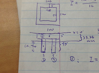
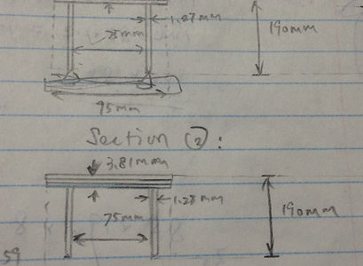

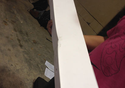

Figure 1: Corresponding Design Phases
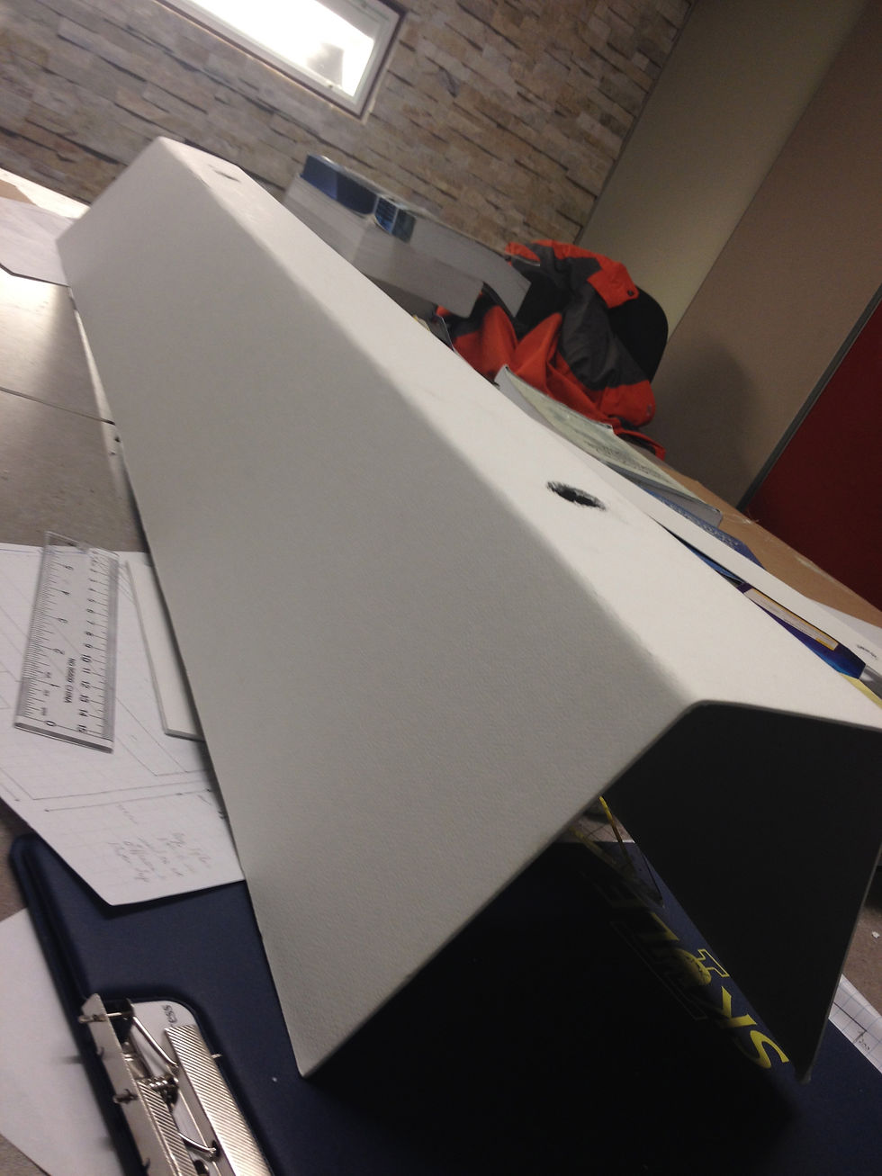


Figure 2: Preliminary designs.
All dimensions were arbitrary, and only used for rough calculations. After careful analysis and discussions, the bottom design was chosen since the matboard is able to withstand more tension than compression (when the load is applied, the tension is below the axis drawn on the graph), hence less material is needed at the bottom.
Figure 3 (bottom-left):
Determine the actual dimensions of the cross-section

Figure 4 (bottom): After further consideration, we decided to change the design again. For the previous one (Figure 3), the area between the flange and web members is insufficient, therefore less glue can be applied. The bridge might fail because of glue. However, the above design avoids this problem since the flange and web become an unity (Fold the matboard to a U-shape).
Figure 6 (top-left): Bridge after destruction test
Our predicted load is 1488N but the bridge failed at 853N. This is because the most important diaphragms (directly under the load) were detached when increasing the load, thus the bridge failed due to shear at web members. We can avoid this problem by increasing the contact area between web members and diaphragms, and measuring the dimensions more carefully so they can fully attach.
Figure 7 (left): Bridge after destruction test
We can see that the failure occurs only at the diaphragm part, other components remain intact. A small construction problem can reduce the failure load tremendously.
2013/12